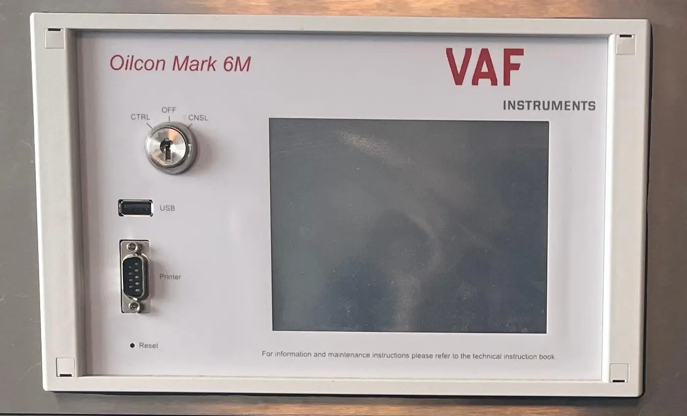
OILCON Mark 6M VAF
The Oil Discharge Monitoring and Control System (ODME) is fitted on oil and chemical tankers for the purpose of monitoring and controlling the discharge of water mixed with oil. One of the main purposes of the system is to allow the controlled discharge of oily water and reduce the amount of slop remaining onboard.
MARPOL Requirements
According to Regulation 31 of MARPOL Annex I, all oil tankers of 150 gross tonnage and above must be fitted with an approved ODME system.
Chemical tankers carrying oil or oil-like substances covered under MARPOL Annex I are also subject to the same operational discharge and monitoring requirements.
The ODME system automatically monitors, records, and controls the discharge of oily water or ballast from cargo tank areas.
The main components of an ODME system are:
Oil Content Meter (OCM): Measures the oil concentration in the discharged water in parts per million (ppm).
Flow Meter: Measures the discharge flow rate.
Computing / Processing Unit: Calculates the instantaneous rate of discharge, records the necessary information, and uses data such as ship speed and position to control the system.
Overboard Control System: Controls the overboard and slop tank valves. If the discharge conditions are outside the permitted limits, the system automatically stops the overboard discharge and diverts the flow back to the slop tank.
Discharge Limits Outside Special Areas
An oil tanker may discharge oily mixtures or ballast from cargo tank areas into the sea outside Special Areas only when all the required conditions are fulfilled.
The main conditions are:
En Route: The tanker must be proceeding on a voyage.
Distance from Land: The tanker must be more than 50 nautical miles from the nearest land.
Instantaneous Rate of Discharge: The instantaneous rate of oil discharge must not exceed 30 litres of oil per nautical mile.
Total Quantity Limit: The total quantity of oil discharged into the sea must not exceed 1/30,000 of the total quantity of the particular cargo of which the residue formed a part, for tankers delivered after 31 December 1979.
Operational ODME: The vessel must have a fully operational ODME system and the required slop tank arrangement.
Special Areas
Discharge of oil or oily mixtures from cargo areas is generally prohibited within MARPOL Special Areas, such as the Antarctic, Mediterranean, Baltic and Red Seas, regardless of whether an ODME system is installed.
There are only limited exceptions, such as certain clean or segregated ballast conditions, depending on the applicable MARPOL requirements.
Data Recording and Retention
The ODME system must have a dedicated recording device that continuously records important information related to the discharge operation.
The recorded information includes:
- Discharge rate in litres per nautical mile
- Total quantity of oil discharged
- Date and time
- Geographical position
Printed or digitally stored records must be retained onboard for at least three years.
ODME Testing and Functional Checks
Like other important equipment onboard, the ODME system also requires regular testing and condition checks.This test procedure should be done under chief officer responsibilities.
Monthly functional tests should be carried out for the valves, system operation, and different alarm or operating conditions. The tests and relevant results should be recorded in the Oil Record Book Part II as required.
So, what exactly should be tested and what procedure should be followed?
On my vessel, we have an OILCON Mark 6M VAF ODME system, and in this article we will look at the test procedure for this particular equipment according to the manufacturer’s instructions.
Important: The following procedure is based on the equipment manufacturer’s instructions. Always follow the actual manufacturer’s manual and the vessel’s approved procedures when carrying out an ODME test.
Test and Check-Out Procedure
Before starting the test, there is one very important point.
Under no circumstances should the pump run without liquid.
The pump housing must first be filled with liquid. Otherwise, the pump can seize and become damaged.
Before carrying out a test, the person in charge should be familiar with the operation of the system and make sure that the following conditions are fulfilled:
- Control air supply is ON.
- Fresh water supply is ON.
- Electrical supplies are ON.
- Main Control Unit (MCU) is switched ON.
- Electro-pneumatic unit is switched ON.
- Starter box is switched ON.
- All manual valves in the system are open.
- Cargo pump is on standby.
Generally, if the vessel is operating in an area where the temperature does not normally fall below approximately 5°C, the air and fresh water supplies can normally be left open after joining the vessel. This avoids problems caused by frozen water in the lines or loss of air supply.
Once these supplies are closed, problems can occur later when the system is required to operate again, so it is better to keep them available when the vessel’s operating conditions allow it.
Functional Test Procedure
Proceed as follows.
1. Initial Setup
1. Turn the key switch to the CONTROL position.
2. Press the SETUP key to enter the setup mode.
3. Press the CHANGE key and then press the NEXT key until “TOTAL OIL LIMIT” is displayed.
4. Change the TOTAL OIL LIMIT to 40 litres.
5. Press the NEXT key to display “RESET OIL TOTAL”.
6. Change RESET OIL TOTAL to YES.
7. Press the NEXT key until “SHIP SPEED INDICATION” is selected. Use the + and – keys to change the ship speed to 15 knots.
8. Press the NEXT key until “FLOW RATE INPUT” is selected. Use the numeric keys to enter a flow rate of 250 m³/h.
9. Press the NEXT key until “OIL CONCENTRATION INDICATION” is selected. Use the numeric keys to enter an oil concentration of 100 ppm.
10. Press the OK key to enter the setup mode.
11. Press the FLUSH key. The system will not perform the normal flush sequence but will immediately go into IDLE mode.
12. Press the SAMPLE key to start the Sample mode.
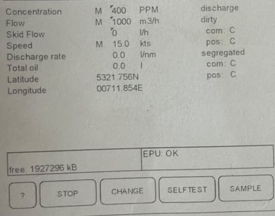
13. Check the display on the MCU and make sure the information shown is correct.
Overboard Valve Operation
14. After approximately 20 seconds, the signal to open the overboard valve and close the slop tank valve will be given. This will be indicated on the MCU display.
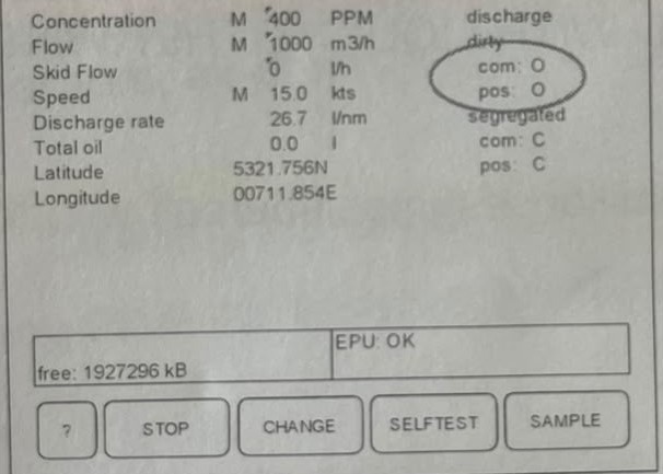
15. Check that the valves have actually operated. On the MCU display, this should be indicated by the valve position changing from C (Closed) to O (Open).
16. Press the STOP key. The system will return to IDLE mode and the signal to close the overboard valve and open the slop tank valve will be given.
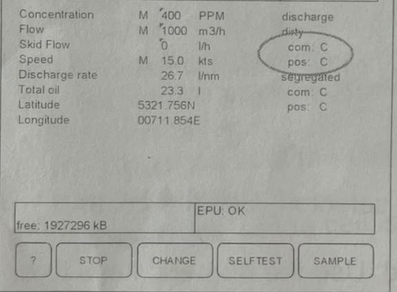
17. Check that the valves have actually operated.
High Flow Rate Alarm Test
18. Select the IDLE setup mode by pressing the CHANGE key.
19. Press the NEXT key until “FLOW RATE INPUT” is selected. Use the numeric keys to enter a flow rate of 2,000 m³/h.
20. Press the OK key and then the BACK key to return to IDLE mode.
21. Press the SAMPLE key to start the Sample mode.
22. Check the display on the MCU for correct information.
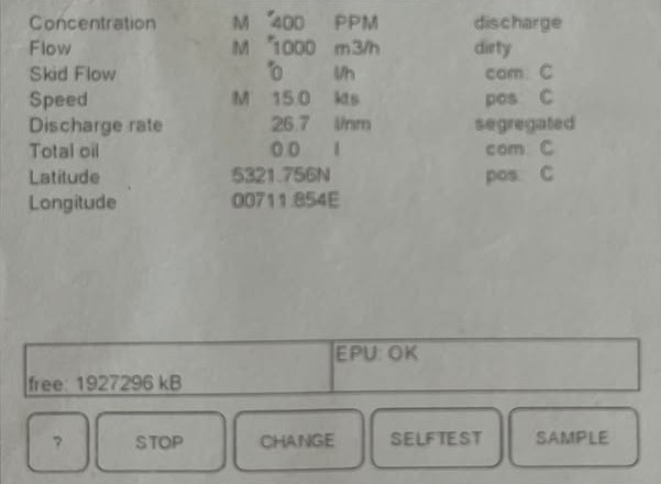
23. Select the Sample mode by pressing the SAMPLE key. Since the discharge rate is now set too high, the system should trigger an alarm.
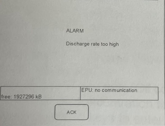
The overboard discharge valve signal should not change from CLOSED to OPEN.
24. Press the ACK key to stop the alarm buzzer.
25. Press the STOP key to return to IDLE mode.
Total Oil Limit Test
26. Select the IDLE setup mode by pressing the CHANGE key.
27. Press the NEXT key until “FLOW RATE INPUT” is selected. Use the numeric keys to enter a flow rate of 1,000 m³/h.
28. Press the OK key and then the BACK key to enter IDLE mode.
29. Press the SAMPLE key to start the Sample mode.
30. Check the display on the MCU for correct information.
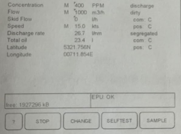
31. Select the Sample mode by pressing the SAMPLE key.
32. Press the SAMPLE key again to start the Sample mode.
33. Check the display on the MCU for correct information.
34. After approximately 2 minutes, the signal to open the overboard valve and close the slop tank valve will be given. This will be indicated on the display.
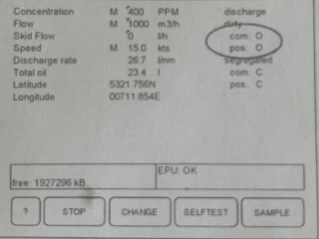
35. Check that the valves have actually operated. On the MCU display, the valve position should change from C to O.
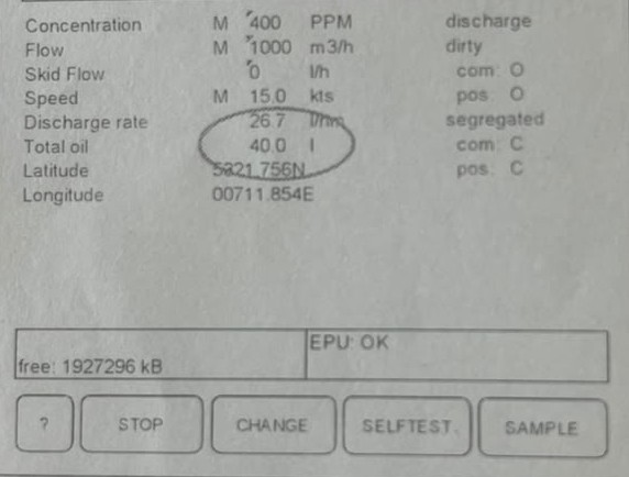
36. The discharged oil quantity shown on the display as “TOTAL OIL” will increase.
Allow the simulated oil discharge to continue until it reaches 40 litres. At this point, the system should give the signal to close the overboard valve and open the slop tank valve, and an alarm should be triggered.
Practical Tip
If you do not want to wait for too long during the test, because this simulation can take around 20–25 minutes, you can increase the flow rate to maximum and reduce the ship speed to around 7 knots.
This will increase the calculated oil discharge rate, allowing the total oil limit to be reached faster. With this method, the alarm can normally be observed within a few minutes.
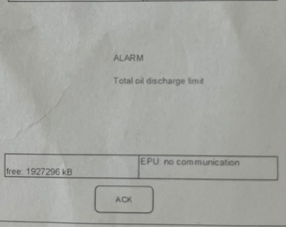
37. Check that the valves have actually operated.
38. Press the ACK key to stop the alarm buzzer.
39. Press the STOP key to return to IDLE mode.
40. Press the STOP key again to select the shutdown mode.
After the shutdown sequence has finished, the system should be in STANDBY mode.
Additional Detailed Test Procedure
The procedure below is taken from the manufacturer’s instruction manual and is more detailed.
For a normal monthly functional test, the procedure above should generally be sufficient for the required operational checks and recording in the Oil Record Book, subject to the vessel’s SMS and applicable requirements.
The more detailed procedure below may be carried out during annual service and maintenance or during other scheduled service intervals, depending on the equipment certificate and manufacturer’s requirements.
Detailed System Test
41. Press the SETUP key to enter the setup mode.
42. Press the CHANGE key and then press the NEXT key until “RESET OIL TOTAL” is displayed.
43. Change RESET OIL TOTAL to YES.
44. Press the NEXT key until “SHIP SPEED INDICATION” is selected. Use the + and – keys to change the ship speed to AUTOMATIC.
45. Press the NEXT key until “FLOW RATE INPUT” is selected. Use the numeric keys to change the flow rate to AUTOMATIC.
46. Press the NEXT key until “OIL CONCENTRATION INDICATION” is selected. Change the oil concentration indication to AUTOMATIC.
47. Use the numeric keys to enter an oil concentration of 400 ppm.
48. Press the OK key to enter the setup mode.
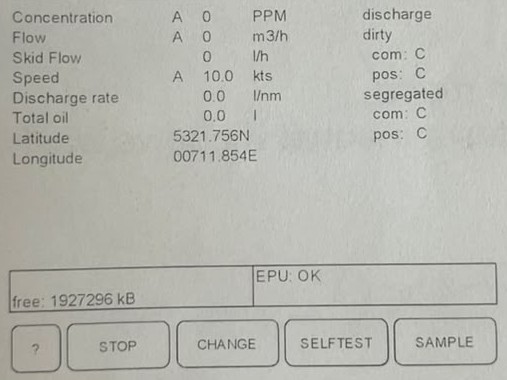
49. Press the FLUSH key. The system will now perform the flush sequence, which takes approximately 7 minutes. After the flush sequence has finished, the system will return to IDLE mode.
50. Check the display on the MCU for correct information.
Sample Pump and Sample Point Test
51. Start the cargo pump.
Note: The MCU will divert the flow into the slop tank.
52. Press the SAMPLE key to start sampling. Check that the ppm indication on the MCU is changing.
53. Press the STOP key to stop sampling and select IDLE mode.
54. Press the CHANGE key to select the IDLE setup mode.
55. Press the CHANGE key to select the SAMPLE POINT. Use the + and – keys to change to the next sample point.
56. Press the OK key and then the BACK key to return to IDLE mode.
57. Press the SAMPLE key to start sampling.
Check the following:
- The correct sample point is indicated on the MCU.
- The correct sample probe is selected.
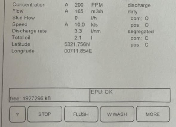
58. Repeat steps 52 to 57 for each sample point.
59. Press the STOP key to stop sampling and select IDLE mode.
Oil Type Selection Test
60. Press the CHANGE key to select the IDLE setup mode.
61. Press the CHANGE key and then press the NEXT key until “OIL TYPE” is displayed.
62. Use the + and – keys to select the next oil type.
63. Press the OK key and then the BACK key to return to IDLE mode.
64. Check that the correct oil type is indicated on the MCU.
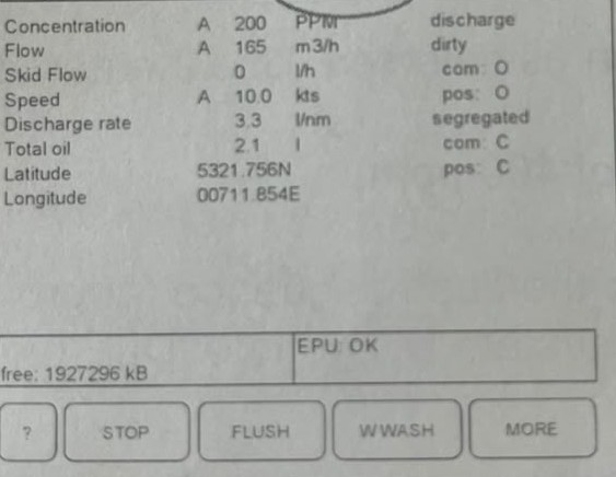
65. Repeat steps 60 to 63 for each available oil type.
Window Wash Test
66. Press the SAMPLE key to select the Sample mode.
67. Press the W WASH key to select the Window Wash mode.
68. After the W WASH key is pressed, the system will initiate a manual window wash sequence to keep the detector cell in good condition.
The display should indicate WINDOW WASH.
Manual Flush and No Flow Alarm Test
69. Press the SAMPLE key to select the Sample mode.
70. Press the FLUSH key to select the manual flush mode.
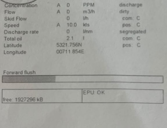
Check the following:
- Valve V10 opens for approximately 2 minutes.
- The oil content indication on the MCU reads zero.
71. Test the NO FLOW alarm by manually closing the sample inlet valve on the skid assembly.
- Check that the sample pump stops after approximately 2 minutes.
- Re-open the sample inlet valve after the test.
72. Check that ship speed, flow rate, and oil content are all displayed on the MCU.
Wait for the overboard discharge valve to open.
Regulate the cargo pump speed and back pressure to obtain a flow rate equivalent to approximately 50% of the rated capacity of the flowmeter.
Underrange Alarm Test
73. Test the underrange alarm by reducing the flow.
Close the overboard valve. The recirculating valve should open.
Increase the discharge flow and press ALARM RESET.
Then press STOP RESET.
Self-Test
74. Press the SELFTEST key to select the self-test mode.
Follow the instructions shown on the MCU display to perform the self-test.
The following should occur:
- The display should indicate 500 ppm.
- The audible alarm should sound.
75. Press the BACK key to return to Sample mode.
76. Press the STOP key to select IDLE mode.
Manual Valve Control Test
77. Turn the key switch on the MCU to the CONSOLE position and check the manual control of the overboard discharge valve and slop tank valve from the cargo control console.
78. Turn the key switch on the MCU to the CONTROL position and check that manual control of both the overboard discharge valve and slop tank valve from the cargo control console is not possible.
Shutdown and Flushing Cycle
79. Press the STOP key to select the shutdown mode.
Check the operation of the shutdown flushing cycle as follows:
- Valve V10 and valve V11 open.
- The sample pump runs.
- After approximately 2 minutes, valve V11 should close.
- The window wash pump should operate for approximately 12 seconds.
- After a further 2 minutes, valve V10 should close and the pump should stop.
- The system should now be in STANDBY mode.
80. Finally, inspect the complete system for any evidence of leakage.
During a monthly functional test, the main purpose is to confirm that the ODME system, valves, alarms, sampling system, and automatic stopping/diverting functions are operating correctly.
Always carry out the test according to the manufacturer’s manual, the vessel’s SMS, and the applicable MARPOL requirements.
For the OILCON Mark 6M VAF system, the procedure above gives a practical example of how the system can be checked under different simulated operating conditions, including high flow, total oil limit, sampling, no-flow alarm, underrange alarm, self-test, valve operation, window washing, and shutdown flushing.